 Allen
Datagraph 800 Plus Series Cutters
November 6, 2009
The Allen Datagraph 800 Plus Series cutters are cut only devices, and are only
available if the special registration code, "CUTTING", is enabled.
Consult the cutter's user manual for information on setting the cutter's force,
speed, and other available options.
Note: To insure consistent cutting,
setup must be run on the cutter. Load the Allen Remote Panel for Allen
Datagraph Systems. Click on "Diagnostics" and follow the instructions to
perform "Calibrate to printer" and "Smartmark Setup." Whenever a change
in media or print resolution occurs, you must perform a "SmartMark Sensor
Setup" (see below). This Series of cutters can only use 1/4" Allen Datagraph marks. Only choose these marks when printing.
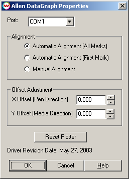
This device is a serial-only device. The COM port setting can be found by
clicking on the Properties button on the Print/Configuration tab. The following
window will be displayed:

Port:
Choose the COM port that the cutter is connected to. (See note below)
Note: Do not attempt to use this cutter on any COM port which is in use
by the Palm HotSync Manager. If you run into any conflicts with the HotSync
manager, please reconfigure it to use a different port and reboot your
computer.
Alignment:
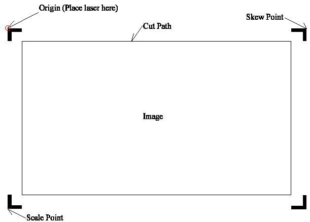
Automatic Alignment (all marks): This choice will perform skewing
and scaling on the image. There must be Allen DataGraph type registration
marks. Place laser as shown below.
Automatic Alignment (one mark): This choice will align the origin
with one mark. There must be Allen DataGraph type registration
marks. Place laser as shown below.
Manual Alignment: If there are either Allen DataGraph marks
or Wasatch marks (1/4 Inch Register or 1/2 Inch Register), the driver will go
through a manual alignment set up (see image below). This image will be upside
down when looking at the front of the cutter. For Allen Datagraph marks,
align the sensor with the outside corner of the mark. Center the sensor
with Wasatch type (1/4 Inch Register or 1/2 Inch Register) marks.

Note: If there are Allen DataGraph marks that are not found when an
automatic alignment is performed. There will be a choice whether to
continue or abort the cut.
Offset Adjustment:
Use the X and Y values of the offset adjustment to fine tune the cutters
offset. This is here so one does not have to go into the Allen Remote Panel to
make small changes.
Device-Specific Instructions for Loading Print and then Cut Jobs
You must insert the media from the rear of the cutter. Inserting the media from
the back, the cutting registration marks #1 (origin) and #2 (skew) should be on
the edge of the print closest to the front of the printer.
Since the cutter cannot cut any media beyond the pinch roller nearest the
control panel, align the media so that the pinch roller is over the left
margin, but not over any part of the print that is to be cut.
Many devices are shipped with the paper sensors turned off. Assuming this is
the case, you can press "Load" on the front panel of the printer when no media
is inserted. After it finishes moving the head, lift the pinch rollers, and
place the media into the cutter.
If the paper sensors are on, you will have to have media inserted before you
hit the "Load" button.
After lowering the pinch roller, go back to the computer, and click on Print,
then Configuration, then Properties. The properties sheet (shown above) will be
displayed. Choose the correct COM port that the cutter is connected to.
Choose the alignment method.
The cutter is now ready for the cut path to be sent from the Cutting Queue.
SmartMark Sensor Setup
The "Two Level Teaching Mode" will allow one to set a middle ground threshold
value for the SmartMark Sensor.
-
Open the panel on the top of the SmartMark Sensor. There is a "Mode" button
with a dial to the left. This dial is referred as the "jog" switch.
-
Select the "TEACH" mode by pressing the Mode Key once.
-
Move the LED to the background material and press the jog switch. The display
will blink then the "TEACH" (yellow light) will blink. This indicates that the
second point is now ready for input.
-
Move the sensor over the origin target you want sensed, press the jog switch,
again the display will blink.
-
The display will either indicate the word "good" which indicates that stable
sensing can be performed or "hard" indicating stable sensing cannot be
performed. The threshold value setting will be displayed then the display will
blink with the character "----". The incident light intensity will again
be displayed, indicating that the configuration is now complete. Press the
"Mode" key 5 times or keep it pressed for 2 seconds or more to return to "RUN"
mode.

