 Graphtec FC5100 Cutter
October 22, 2008
The Graphtec FC5100 is a cut only device, and is only available if the special registration code, "CUTTING", is enabled.
Consult the cutter's user manual for information on setting the cutter's origin point, force, and speed.
Important Note: Initial Setup of the Plotter's Front Panel
Controls:
Basic set up should be performed to make sure that the plotter is in the correct state to receive data from SoftRIP. This Basic Setup needs to be performed only once, but it must be performed before sending any data to the cutter. Please refer to the section titled "Basic Setup of the Graphtec FC5100" near the bottom of this web-page for more information.
Connection: Choose the physical connection from the 'Print->Setup' window.
- USB: When you first plug the cutter into a USB port you will be prompted for a USB driver. The driver is included on the CD labeled "Disk 1 Application" in the folder "Misc/Graphtec USB". A USB connection option will not appear on the "print/setup" window unless the Graphtec cutter is actually connected with the USB cable. The first FC5100 will get the number "00". Each plotter connected will get a new number (i.e. FC5100-01) and will maintain that number even when disconnected.
- COM: Choose the COM port to which the serial cable is connected.
- LPT: Wasatch SoftRIP does not support the parallel interface for this device.
Note: There are three methods to have the cutter detect the Graphtec type registration marks. The first lets the registration come from the RIP. The second two methods register the print at the time the media is inserted into the cutter. Go to the properties page (Print->Setup->Edit->Properties) to set up which mode to use. Choose "RIP Detect" to register automatically at the time the job is sent. Choose "Front Panel Setup" for all other options. This setting will remain the same in-between jobs. There is no need to reset if the mode remains the same.

-
Device-Specific Instructions for Print now, Cut Later (RIP Detect Registration)
Note: The print should have been printed with "Graphtec Type 1", "Graphtec Type 2" or "Graphtec 1/2" Interval" Register marks. These marks can be selected from the "Cutting Mark" menu on the Print/Setup screen prior to printing.
Loading the media:

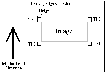
- As the print comes off the printer, note the edge that is to the lower right corner of the print. That corner will be referred to hereafter as the origin (TP1) of the print (see illustration above).
- Insert the media in the same direction as the media originally came out of the printer. Since the cutter cannot cut any media beyond the pinch roller nearest the control panel or the pinch roller furthest from the control panel, align the media so that the pinch rollers are outside of the cutting area.
- After setting the pinch roller,
- For firmware version 2.0
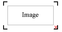
depending on setup, you may have to press "Skip" (see Mark Scan Mode below to disable), then press "Sheet" or "Roll" to choose paper. Align the knife in the open area bounded by the first mark (TP1) as shown to the right. Press Origin.
- For firmware version 5.31
press "Sheet" or "Roll" to set paper type. Align the knife in the open area bounded by the first mark (TP1) as shown to the right. Press Origin.
- In SoftRIP, go into properties (Print->Setup->Edit->Properties) and choose "RIP Detect"
- The cutter is now ready for the cut path to be sent from the Cutting Queue. See the user manual for further assistance.
-
Device-Specific Instructions for Print now, Cut Later. Firmware version 5.31 and later (Full Automatic Registration)
Note: As of firmware revision 5.4, the plotter can use four points with this registration method. If you are using firmware revision 5.4 or later, this method may result in the most accurate contour cuts.
Note: The print should have been printed with "Graphtec Type 1" or "Graphtec Type 2" Register marks. These marks can be selected from the "Cutting Mark" menu on the Print/Setup screen prior to printing. 
Note: To use this method you will need to measure the distance between the registration marks before loading the paper into the cutter.
Loading the media:
- As the print comes off the printer, note the edge that is to the lower right corner of the print. That corner will be referred to hereafter as the origin (TP1) of the print (see illustration above).
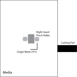
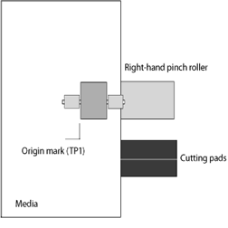
- Insert the media in the same direction as the media originally came out of the printer. Align the media so that the pinch roller closest to the control panel is about 1/4 inch to the left of the vertical edge of the first mark (TP1) and that the horizontal edge of the mark is on or in front of the Cutting pad (See image).
- Make sure scan mode is set up (see Set Mark Scan Mode below)
- After setting the pinch roller, select "Roll 2" as the media detection option
- Press "Axis Alignment" and choose "Auto". The marks will be detected.
- Press Origin
- In SoftRIP, go into properties (Print->Setup->Edit->Properties) and choose "Front Panel"
- The cutter is now ready for the cut path to be sent from the Cutting Queue. See the user manual for further assistance.
-
Device-Specific Instructions for Print now, Cut Later. Firmware version 2.0 and earlier (Full Automatic Registration)
Note: The print should have been printed with "Graphtec Type 1" or "Graphtec Type 2" Register marks. These marks can be selected from the "Cutting Mark" menu on the Print/Setup screen prior to printing. 
Note: To use this method you will need to measure the distance between the registration marks before loading the paper into the cutter.
Loading the media:
- As the print comes off the printer, note the edge that is to the lower right corner of the print. That corner will be referred to hereafter as the origin (TP1) of the print (see illustration above).
- Measure the distance between mark 1 and mark 2. Measure the distance between mark 1 and mark 3.
- Insert the media in the same direction as the media originally came out of the printer.
Note: Since the cutter cannot cut any media beyond the pinch roller nearest the control panel or the pinch roller furthest from the control panel, align the media so that the vertical edge of the first mark (TP1) is in line with the left brass bushing of the pinch roller closest to the control panel.
- Make sure scan mode is set up (see Set Mark Scan Mode below)
- After setting the pinch roller, press "Auto" and the marks will be detected.
- If needed, enter the correct measurements taken above
- In SoftRIP, go into properties (Print->Setup->Edit->Properties) and choose "Front Panel"
- The cutter is now ready for the cut path to be sent from the Cutting Queue. See the user manual for further assistance.
-
Device-Specific Instructions for Print now, Cut Later (Manual Registration)
Important Note: This registration method may result in less accurate contour cuts than the Full Automatic and RIP Detect registration methods.
Note: The print should have been printed with 1/4" or 1/2" Register (Not Graphtec) marks (1/2" are preferred). Select these marks from the "Cutting Mark" menu on the Print/Configuration screen.
Loading the media:
- As the print comes off the printer, note the edge that is to the lower right corner of the print. That corner will be referred to hereafter as the origin (TP1) of the print (see illustration above).
- Insert the media in the same direction as the media originally came out of the printer.
Note: Since the cutter cannot cut any media beyond the pinch roller nearest the control panel or the pinch roller furthest from the control panel, align the media so that the pinch rollers are outside of the cutting area.
- After setting the pinch roller,
- Firmware 2.0
depending on setup, you may have to press "Skip" (see Mark Scan Mode below to disable), then press "Sheet" or "Roll" to choose paper.
- Firmware 5.31
press "Sheet" or "Roll" to set paper type.
- Align the knife with mark #1. Press Origin.
- In SoftRIP, go into properties (Print->Setup->Edit->Properties) and choose "Front Panel"
- The cutter is now ready for the cut path to be sent from the Cutting Queue.
- When the path is sent, an information screen will ask you to align point #1
- Use arrow keys to make sure knife is centered on mark and press "Enter"
- The knife will move to next point. Use arrow keys to fine adjust and press "Enter"
- The knife will move to the final point. Use arrow keys to fine adjust and press "Enter"
- Cutting will now proceed.
-
Device-Specific Instructions for Cut Only
Loading the media:
- Insert the media in the cutter and align the media so that the pinch rollers are outside of the cutting area.
- After setting the pinch roller,
- Firmware 2.0
depending on setup, you may have to press "Skip" (see Mark Scan Mode below to disable), then press "Sheet" or "Roll" to choose paper.
- Firmware 5.31
press "Sheet" or "Roll" to set paper type.
- Use arrow keys to place the knife over the desired starting point.
- Press "Origin"
- In SoftRIP, go into properties (Print->Setup->Edit->Properties) and choose "Front Panel"
- The cutter is now ready for the cut path to be sent from the Cutting Queue.
-
Basic Setup of the Graphtec FC5100
The following instructions explain how to properly set your plotter up for use with Wasatch SoftRIP. Please be sure to use the instructions for your firmware revision as there are slightly different options and settings available.
Basic Setup For Firmware Version 5.4 or later
- Set Distance Adjust
- Axis Alignment
- F1 (Auto Reg Mark)
- F4 (Distance Adjust)
- F2 (OFF)
- Enter
- Set Mark Type
- Axis Alignment
- F1 (Auto Reg Mark)
- F2 (Mark Type)
- F4 (Type 2)
- Enter
- F3 (Other Setups)
- F1 (Mark Size)
- Set mesurement to match selected mark type
- Enter
- Set Mark Scan Mode
- Axis Alignment
- F1 (Auto Reg Mark)
- F1 (Mark Scan Mode)
-
- Enter
-
- F2 (2 Mark)
- F3 (3 Mark)
- F4 (4 Mark)
- Enter
- Scan Mark
- F1 > 1
- F2 > 2
- F3 > 3
Note: The Scan Mark setting allows you to specify areas that the plotter will not sense by specifying the distance between the registration marks. Once the plotter locates the first registration mark, it will automatically move the specified distance and begin scanning for the next mark. You can also use this function to reduce mark-sensing time, though before you begin, you must know the distance between registration marks. If you wish to have the plotter scan the full length and width of the media, simply set the X and Y values to 0. This will increase the time it takes to scan for the registration marks, but does not require you to know the exact length and width of your cut job. Consult the plotter's documentation for further information on this feature.
- Next (to accept the current setting) or Enter (to adjust the Scan Mark setting)
- Set For Program control
- Menu
- Next
- Next
- Next
- F2 (Background)
- Next
- Next
- F4 (Program)
- Enter
- Menu
- Set Command Mode
- Menu
- Next
- Next
- F1 (Interface)
- F4 (Command)
- F4 (HP-GL)
- Enter
- Menu
Basic Setup For Firmware Version 5.31
- Set Distance Adjust
- Axis Alignment
- F1 (Auto Reg Mark)
- F4 (Distance Adjust)
- F2 (OFF)
- Enter
- Set Mark Type
- Axis Alignment
- F1 (Auto Reg Mark)
- F2 (Mark Type)
- F4 (Type 2)
- Enter
- F3 (Other Setups)
- F1 (Mark Size)
- Set mesurement to match selected mark type
- Enter
- Set Mark Scan Mode
- Axis Alignment
- F1 (Auto Reg Mark)
- F1 (Mark Scan Mode)
-
- Enter
-
- F2 (2 Mark)
- F3 (3 Mark)
- F4 (4 Mark)
- Enter
- Set For Program control
- Menu
- Next
- Next
- Next
- F2 (Background)
- Next
- Next
- F4 (Program)
- Enter
- Menu
- Set Command Mode
- Menu
- Next
- Next
- F1 (Interface)
- F4 (Command)
- F4 (HP-GL)
- Enter
- Menu
Basic Setup For Firmware Version 2.0 and earlier
- Set Mark Type
- Menu
- Next
- F1 (Auto Reg Mark)
- F2 (Mark Type)
- F4 (Type 2)
- Enter
- F3 (Other Setups)
- F1 (Mark Size)
- Set mesurement to match selected mark type
- Enter
- Menu
- Set Mark Scan Mode
- Menu
- Next
- F1 (Auto Reg Mark)
- F1 (Mark Scan Mode)
-
- F2 (Disable)
- F3 (2 Points)
- F4 (3 Points)
- Enter
- Menu
- Set For Program control
- Menu
- Next
- Next
- Next
- F2 (Background)
- Next
- Next
- F4 (Program)
- Enter
- Menu
- Set Command Mode
- Menu
- Next
- Next
- F1 (Interface)
- F4 (Command)
- F4 (HP-GL)
- Enter
- Menu
 Graphtec FC5100 Cutter
 Graphtec FC5100 Cutter

