Mimaki JV3 Mimaki JV3
*The JV3(Dual CMYK) modes have been added for use with the JV3-SP when two sets of CMYK ink are loaded.
Note: Max Printing Widths
To ensure that data from Wasatch SoftRIP is correctly processed, the following setting is
REQUIRED on the front panel of the JV3 printer:
Important: Firmware requirements:
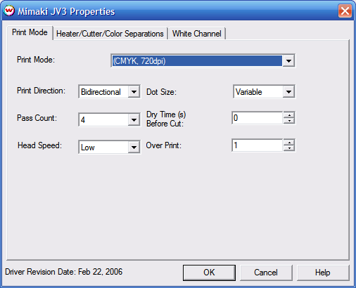
Print Mode:
To launch the printer properties for this driver, choose 'Setup' from the 'Print' menu, then select
Mimaki JV3 in the 'Printer Model' list, click on the 'Edit' button, and then click on 'Properties'.
The heater, cutter, and color separation controls are located on the second tab. The separations controls
are only available when using Monochrome modes.
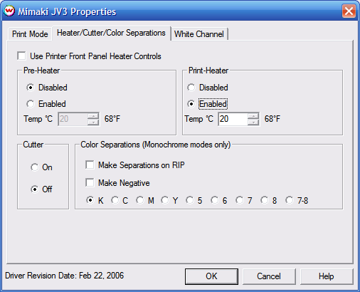
The heater controls are used to dry prints faster. If you have Use Printer Front Panel Heater
Controls checked, the software does not control the heaters. If it is unchecked, you have the
option to disable, or enable the heater at a certain temperature. If the heater is enabled, the
heater will not be turned off at the end of the print, so that the heater remains at a constant
temperature for the following print.
Note: With Mimaki's SS2 inkset it is recommended that you have heaters set no higher then
35 degrees Celsius
If the heater controls are enabled, and the current temperature of the heaters is less (or more) than
the temperature setting, the printer will wait before sending the print until the set constant temperature
is achieved. (This may take some time.)
Note: Choosing channel 5 or greater in the color separations section is invalid when dual cmyk
inks are installed in the SP model.
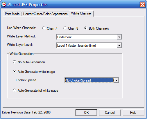
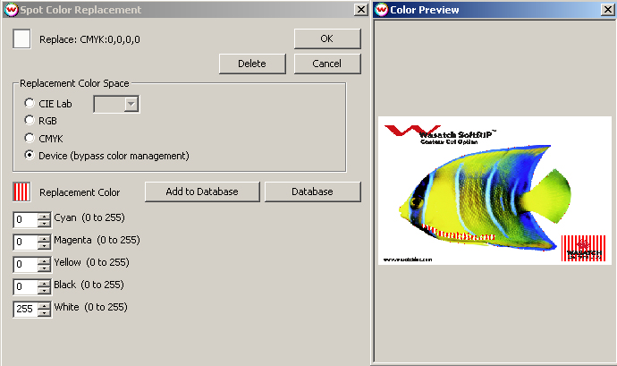
Spot Color replacement can be used with white to designate areas of the print where white should be printed. The steps to use this work flow are:
IEEE 1394 is recommended to ensure an adequate data rate for this printer. Mimaki distributes their own driver component for IEEE 1394, that must be installed in Windows. This driver can also be found on the Wasatch SofRIP CD-ROM. Note that Mimaki's driver is for Windows 2000 or XP only.
Steps on installing Mimaki Firewire
After installing the Mimaki IEEE1394 drivers, go to the Print Setup window in SoftRIP. From the Printer Model menu, select your Mimaki printer. After selecting the Printer Model, select IEEE1394-x in the Physical Connection list (where x is the order that the Mimaki Device was detected, see notes below on Connecting to Multiple Mimaki IEEE 1394 Devices).
The following IEEE 1394 FireWire PCI Adapter cards have been tested at Wasatch and found to work well (every card we've tested thus far works fine):
In addition please be aware of the following precautions provided by Mimaki:
You should perform all of the printer adjustment steps mentioned in this document to ensure optimal printer
operation. You should also perform the following adjustments periodically if the quality of your prints deteriorates.
[HEAD HEIGHT]
Set the Head Height based on the thickness of your media.
[TEST DRAW]
Before continuing with any further adjustments you should make sure that all your heads are firing properly
see the Operation Manual for details.
[PRINTADJUST]
You should also complete the [PRINTADJUST] calibration which can be found in the Operation Manual.
[MEDIA COMP.]
For instructions on printing the [MEDIA COMP.] test pattern please see
the Operation Manual. Below are some specific notes on this adjustment.
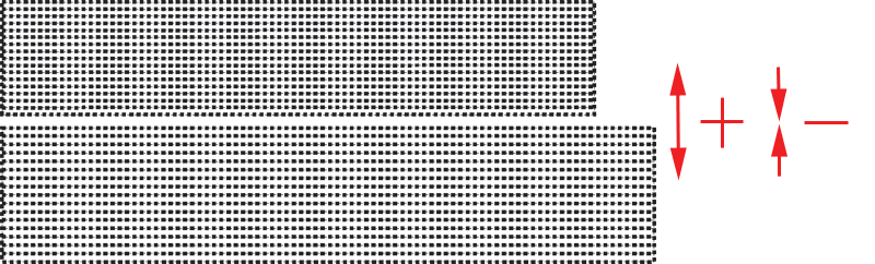
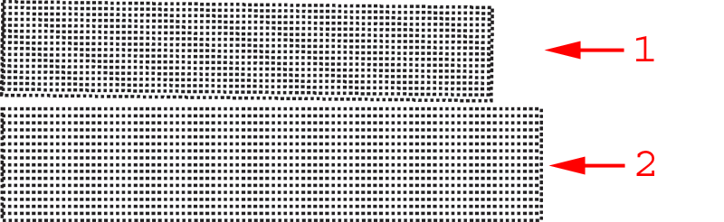
When you print out the [MEDIA COMP.], you should see a pattern similar to the one below.
Look at the gap between the two sections (labeled 1 and 2) in illustration (A).
You should note that the gap is greater on the left side
of the illustration than it is on the right. This is normally a sign that the
media is not feeding through the printer in a straight path. If you see a difference
between the left and right sides of your print, whether it is a gap or an overlap, you
must reload the media. If you run into this problem it may help to feed a little
extra media into the printer and then roll it back slightly onto the roll. This should
straighten it out. Keep repeating the process of reloading the media and printing the [MEDIA COMP.]
until the paper is loaded properly.
Your goal will now be to eliminate any gap or overlap between the two sections.
You can accomplish this by using the keys on the front panel of the printer
to increase or decrease the media compensation value (see the operation manual for details).
Increase the value to move the two sections father apart or decrease the value to move them closer together.
Once you have followed the procedures above, your printer should be well adjusted which will reduce
banding and other printer artifacts. Remember, when you notice the quality of your prints decrease,
follow each of the above steps again.
Note on connecting to multiple Mimaki IEEE 1394 devices:
In order to print over IEEE 1394 to
multiple Mimaki print devices simultaneously, the Mimaki IEEE 1394 driver v2.00 (or later) is required.
To make use of this functionality, each Mimaki device must be connected to a separate IEEE 1394 (FireWire)
PCI Adapter (up to a max of 4). Do not attempt to plug in multiple Mimaki devices into different ports on
the same card, as hardware misdetection and other unexpected results may occur. Also, printing to multiple
devices simultaneously may reduce communication speed somewhat due to the additional access time on your
computers hard disc.
Printer Adjustments:
(A)
(B)