 Cutting with Wasatch SoftRIP Cutting with Wasatch SoftRIP
Get started on setting up your system by reviewing Print and Cut Workflows.
The Wasatch Cutting Option allows SoftRIP to drive print/cut inkjets and standard cutting plotters manufactured by Allen Datagraph, Graphtec, Mimaki, Roland, Zund, and other manufacturers. When the Cutting feature is enabled, SoftRIP will extract cutting paths from PostScript jobs created in Adobe Illustrator and CorelDRAW. In addition, the Wasatch SoftRIP Tracer will extract cutting paths by analyzing preview bitmaps of both vector and raster input files. The following discussion is a general description of how cutting paths are created and exported to SoftRIP. More detailed instructions for creating paths in specific applications are also included in this online help section.
Cutting with Wasatch Tracer
Cutting with Illustrator
Cutting with CorelDRAW
Paths created with a spot color name such as cutpath (default) or your own custom cut color name (e.g. mycut), or cutcontour, will be shown as animated blue-and-white dashed lines on SoftRIP’s preview screen (Illustration C1). When output to a digital cutter or print-and-cut inkjet device, the paths shown will be cut. Illustration C1 shows artwork created for a promotional decal using ordinary colors. The dashed blue lines indicate where the cut path spot color was used. When this job is sent to a print-and-cut device, the color image will be printed, then the knife will cut out the decal on the paths.
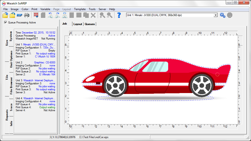
Illustration C1: Artwork shows cutting paths
Additional spot color names can be defined in the Cutting Colors tab of the Preferences window. SoftRIP will treat each custom cut color name (default cutpath or your own custom name) as its own cut path, sending them to the cutter in the listed order and pausing between each path to allow for tool or setting changes. Drag and drop color names to reorder the cutting sequence. For a more complete explanation of this feature see our help page on understanding Cutting Colors.
The controls for contour cutting are located on the Setup menu, as shown in Illustration C2. To activate processing of cut paths from files for a particular print unit, check the Process Cutting Paths box. This activates the workflow based on cut paths, made by common graphics applications. Note: In order for your cutter to be active within the Print>Setup menu, a second print unit must be configured for your cutter, as shown in Illustration C3.
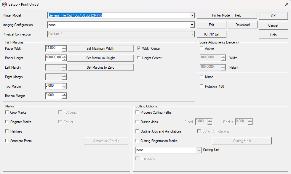
Illustration C2: Cutting Controls
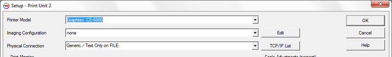
Illustration C3: Cutting Unit Setup
If you’re printing multiple images using the Single Row Nesting or the Layout tab, the cutting path will be correctly duplicated and registered for every copy (Illustration C4).
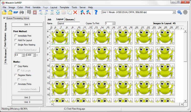
Illustration C4: Nested Images with cutting paths
The Process Cutting Paths tool is not just for print and cut applications. It can also be used with ordinary vinyl cutters for such tasks as cutting lettering with complex paths (Illustration C5).

Illustration C5: Cutting vinyl letters
Checking the Outline Jobs box in the Cutting Options area of the Setup menu causes rectangular cutting paths to be generated at the edges of each image, whether the image is on the Job screen or the Layout screen (Illustration C6a).
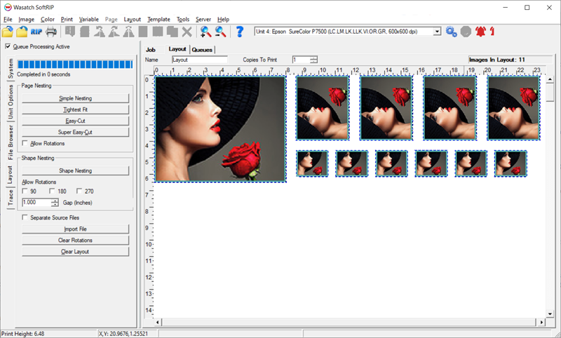
Illustration C6a: Cutting Outline Jobs
The associated controls for Bleed and Radius allow for this outline to be positioned a short distance inside the page, and for round corners to be specified. Any radius greater than zero will generate rounded corners. (Illustration C6b).
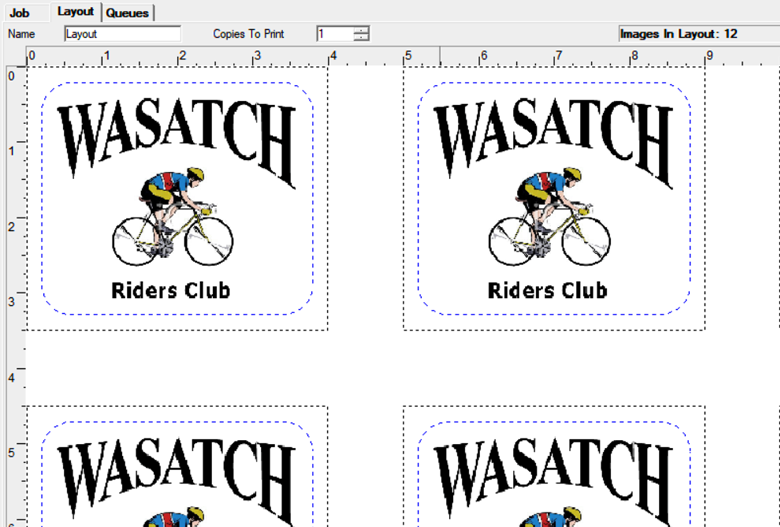
Illustration C6b: Cutting Outline Jobs with Rounded Corners
NOTE: A negative Bleed can be applied to move the outline away from the image, but this is only for images placed on a Layout that have enough space (gap) around them.
This feature can be used together with Process Cutting Paths as well as the Trace feature, to produce weeder boxes. It is also useful for producing work such as a photographic package job shown in Illustration C6.
For instructions on how to prepare your cut path using the Wasatch Trace feature, review the Cutting with Wasatch Tracer section of online help.
Checking the Outline Jobs and Annotations box is similar to Outline Jobs, creating a rectangular cutting path at the top and sides of an image but also includes a cutting path around the Annotations. The additional control for Cut Off Annotations adds another cut path between the bottom of the image and the top of the annotations, to allow the two pieces to be separated later.
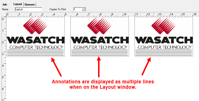
Illustration C7: Outline Jobs and Annnotations
The Rows and Columns option, in the Cutting Options area of the Setup menu, creates cut paths that divide Layouts into rows and columns based on their placement on the layout. This option generates cut lines through the gaps between images, evenly splitting the spacing to produce A Grid Of Cut Lines. The cut lines are visible on the Layout as blue and white dashed lines.
Gap spacing must be greater than 0 for this option to be available. The cut paths are positioned at the midpoint of the gaps between images, and are automatically determined by the number and arrangement of images on the page. In Illustration C8, below, the Gap has been set to 0.75" horizontal value and 1.0" vertical value.
NOTE: The Rows and Columns feature works best when all images are the same size and aligned in a uniform layout. The use of Easy-Cut or Super Easy-Cut nesting options (located on the Layout tab along the left menu bar) are recommended, while using Shape Nesting or Tightest Fit are not as they will produce poor results.
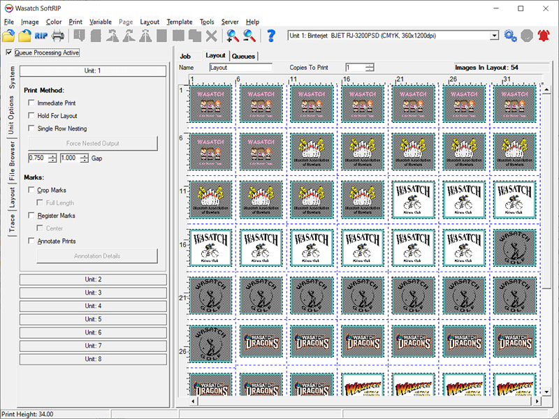
Illustration C8: Rows and Columns
This option can be used in combination with other cut paths, made with the Tracer or Cutting Colors. For example, you can create a contour cut around each image while also applying Rows & Columns to cut a larger rectangular grid, such as when producing peel-off stickers. See Illustration C9.
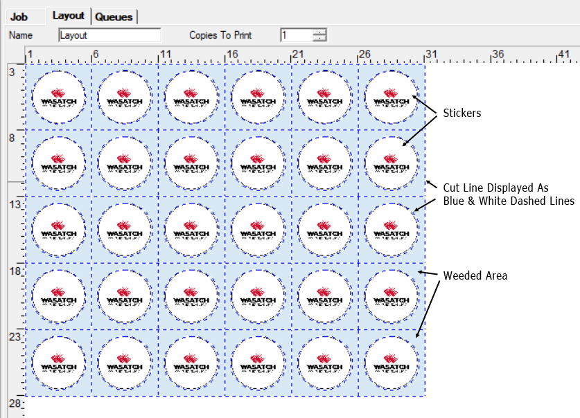
Illustration C9: Creating Labels with Weeded Area